
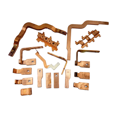
Progressive die and mold technology represents a pinnacle of efficiency in high-volume metal stamping operations. At its core, a progressive die is a specialized tool that performs a series of operations at multiple stations with a single press stroke, progressively transforming a strip of metal into a complex part. This methodology stands in stark contrast to single-stage dies or compound dies, which complete only one or a few operations per stroke. The fundamental principle involves a metal strip, or coil, feeding through the die. With each press stroke, the strip advances to the next station, where a different operation—be it cutting, bending, coining, or drawing—is performed. The final station separates the finished part from the strip, allowing for continuous, high-speed production. The mold, or the die itself, is a marvel of precision engineering, typically constructed from high-grade tool steels to withstand immense pressure and repetitive use. Understanding this foundational concept is crucial for any manufacturing professional looking to optimize their production lines for components like electrical contacts, automotive brackets, or intricate appliance parts.
To fully grasp how a progressive die operates, one must become familiar with its key components. Each part plays a critical role in the seamless execution of multiple operations.
The interplay between these components is what allows for the high-speed, precision manufacturing that progressive dies are renowned for. The design and manufacturing of these components require extreme precision, often measured in microns, to ensure the final produced parts meet stringent quality standards.
One of the most critical decisions in progressive die mold making is the selection of the appropriate tool steel. The choice of material directly impacts the die's longevity, performance, maintenance schedule, and ultimately, the cost-effectiveness of the entire production process. Tool steels are specialized alloys designed to withstand the harsh conditions of metal stamping, including high impact, abrasion, and heat. Selecting an incorrect grade can lead to premature failure, excessive downtime, and poor part quality.
Different applications demand different material properties. For instance, a die primarily used for blanking thin, soft aluminum will have different requirements than one used for forming high-strength steel. The key properties to consider are wear resistance, toughness, and hardness. Wear resistance is crucial for maintaining sharp cutting edges over long production runs. Toughness determines the steel's ability to resist chipping and cracking under high-impact loads. Hardness provides the necessary resistance to deformation under pressure. Often, there is a trade-off between these properties; a very hard steel may be more brittle, while a tougher steel may wear more quickly.
The following table provides a comparison of common tool steel grades used in progressive die making:
| Grade | Primary Characteristics | Ideal Application | Considerations |
|---|---|---|---|
| D2 | High wear resistance, good compression strength | Long-run dies for blanking and forming | Can be susceptible to chipping in high-impact applications |
| A2 | Good combination of toughness and wear resistance | General-purpose stamping and blanking dies | Offers better stability in heat treatment than O1 |
| M2 | High red hardness and wear resistance | Punches and parts generating high heat | Superior performance in high-speed applications |
| S7 | Excellent impact toughness | Heavy-duty forming, coining, and cold extrusion dies | Can be hardened to a high level for good wear resistance |
Beyond material selection, the heat treatment process is equally vital. Proper hardening, tempering, and often cryogenic treatment are essential to unlock the full potential of the chosen steel grade, ensuring it achieves the desired properties for a specific application.
The journey to a successful stamped part begins long before metal is cut; it starts with meticulous design. Design tips for progressive die stamped parts are centered around designing for manufacturability (DFM). This philosophy involves creating part geometries that can be produced efficiently, economically, and with high quality using the progressive die process. Ignoring DFM principles can lead to unnecessarily complex dies, higher tooling costs, production issues, and part failures. A part that looks perfect on a computer screen might be impossible or prohibitively expensive to produce without slight modifications that don't compromise its function.
Engineers must consider several factors when designing a part for progressive die stamping. These considerations guide the design to ensure it is optimized for the process.
Engaging with a experienced die designer early in the product development phase is invaluable. They can provide feedback on how to tweak a design to make it more stamping-friendly, often saving significant time and money down the line.
The longevity and consistent performance of a progressive die are almost entirely dependent on a disciplined and proactive maintenance regimen. A well-executed progressive die maintenance process is not merely a reactive measure to fix problems but a strategic approach to prevent them. Neglecting maintenance leads to unplanned downtime, poor part quality, and catastrophic tool failure, which can cost tens of thousands of dollars in repairs and lost production. A comprehensive maintenance strategy encompasses cleaning, inspection, lubrication, and documentation after every production run or within a set cycle count.
A thorough maintenance routine is systematic and leaves no component unchecked. The goal is to identify and address wear and potential issues before they escalate.
This proactive approach transforms maintenance from a cost center into a valuable investment that maximizes uptime, ensures part quality, and extends the life of a very capital-intensive asset.
Even with a perfectly designed die and a rigorous maintenance schedule, issues can arise during production. Effective troubleshooting is a critical skill for die technicians and press operators. The ability to quickly diagnose and rectify a problem minimizes downtime and scrap. Many common issues have distinct root causes, often related to tooling, material, or the press machine itself. Understanding the troubleshooting progressive die issues methodology is key to efficient production.
Let's explore some of the most common defects encountered in progressive die stamping, their potential causes, and recommended solutions.
A systematic approach—checking the simplest solutions first, such as material specifications and press settings, before moving to complex die disassembly—is the most efficient path to resolving production hiccups.
When evaluating the implementation of a progressive die for a new project, looking beyond the initial tooling price is paramount. The progressive die cost analysis involves calculating the Total Cost of Ownership (TCO), which provides a more accurate picture of the investment over the die's entire lifespan. A cheaply made die can become the most expensive option if it requires constant maintenance, produces high scrap rates, and fails prematurely. Conversely, a well-designed and built die, though higher in initial cost, often proves to be far more economical in the long run.
The TCO for a progressive die is an aggregation of several cost factors, both direct and indirect.
By analyzing these factors together, a manufacturer can make an informed decision that balances upfront investment with long-term operational efficiency and reliability, ensuring the chosen tooling solution delivers the best possible value over its entire service life.
Contact Us
Telphone:+86-15850033223 E-mail:[email protected] Address:No. 2566 Huan Qing Road, Kunshan city, Jiangsu, P.R.CCustom Professional Metal Mold Design & Fabrication Suppliers


